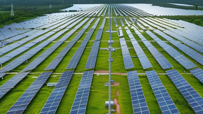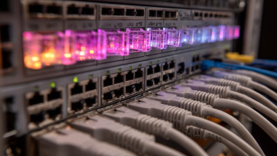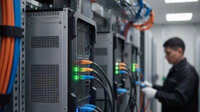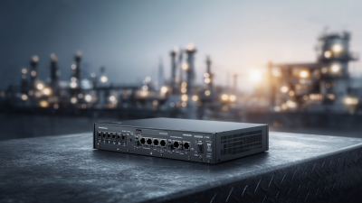
Selecting the right Solar Poe Switch requires more than comparing port counts or advertised wattage. In real deployments, sunlight changes hourly, cable runs create voltage loss, and outdoor enclosures face dust, rain, and heat. A switch that performs well in a laboratory may struggle beside a dusty road or remote security gate. This guide examines leading solar PoE switches through practical installation needs, power efficiency, network stability, and environmental protection.
The strongest options should deliver reliable Power over Ethernet while working smoothly with solar panels, batteries, cameras, access points, and monitoring equipment. We will consider PoE standards, total output, surge protection, operating temperature, and battery compatibility. These details often decide whether a system runs overnight or stops before dawn. Small details matter.
Experience from field-style scenarios also shows that marketing claims need careful checking. “Plug and play” may still require load calculations, grounding, and firmware updates. A compact switch may save space but offer limited expansion. A higher-powered model may provide useful headroom but waste energy during light traffic. No shortlist is perfect. That limitation matters.
Rather than naming one universal winner, this article compares Solar Poe Switch models by application. Remote surveillance, agricultural monitoring, traffic control, and off-grid communications demand different priorities. Readers can then match performance with their panel size, battery reserve, network distance, and local weather. The goal is a dependable decision, not an impressive specification sheet.
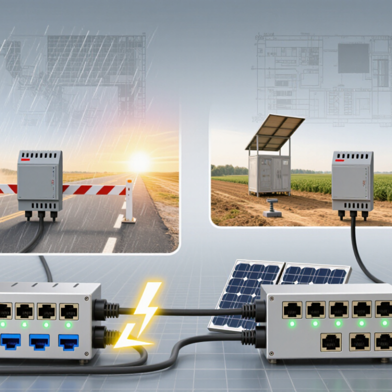
Solar PoE switch selection begins with power standards, not marketing labels. IEEE 802.3af supplies up to 15.4 W per port at the switch. IEEE 802.3at raises that figure to 30 W. IEEE 802.3bt supports roughly 60 to 90 W, depending on its type. These ratings describe switch output, not guaranteed device consumption. Cable losses reduce usable power. A camera may receive less than the printed port rating.
Solar installations need careful energy matching. A switch should accept the battery system’s voltage range and tolerate daily charging changes. It should also provide low standby consumption, efficient DC conversion, and protection against reversed polarity or unstable input power.
In field work, a 30 W port can handle many cameras and access points. High-power radios, heaters, or pan-tilt units may require bt support. Check the device’s real startup demand.
Small details matter. A long outdoor cable can waste power and create voltage drop. Cold mornings can reduce battery capacity, while cloudy weather limits recovery. Oversizing the switch sounds safe, but it may increase idle losses. That choice deserves reflection. The best solar PoE switch combines the required 802.3af, at, or bt output with efficient operation, clear diagnostics, and a power budget based on actual sunlight and load conditions.
What Are the Top Solar PoE Switches?
The top solar PoE switches are not chosen by port count alone. Their real test is daily energy balance. Under IEC 61215, standard test conditions use 1,000 W/m² irradiance, 25°C cell temperature, and AM1.5 sunlight. That rating is useful, but field output is usually lower. NREL’s PVWatts documentation applies a default system-loss assumption of about 14%. Heat, dust, cables, and conversion losses matter.
Use 3–5 peak-sun-hours for an early sizing estimate. A 4-port switch drawing 8 W, plus four 8 W cameras, needs about 40 W continuously. That equals 960 Wh daily. With 3 peak-sun-hours and a cautious 75% overall derating, the array should approach 427 W. At 5 hours, the estimate falls to about 256 W. Add battery capacity for cloudy periods. A little more is safer. Too much, though, raises cost and mounting load.
Tips: Check measured consumption, not only the switch’s maximum rating. IEEE PoE classes describe delivery capability, not the complete solar burden. NREL data also reminds designers that default assumptions are imperfect. Measure winter sunlight locally. The 3–5-hour range can be optimistic in shaded or high-latitude sites. IEA PVPS reported global solar capacity above 1.6 TW by the end of 2023, yet deployment conditions remain highly regional. That difference deserves attention.
| Recommended Profile | Typical Use Case | PoE Standard | Maximum PSE Output per Port | Recommended PoE Port Count | Estimated Continuous Load | Daily Energy Demand | Solar Array at 3 PSH | Solar Array at 5 PSH | Suggested Battery for 2-Day Autonomy | Key Selection Criteria |
|---|---|---|---|---|---|---|---|---|---|---|
| Compact Solar PoE Switch | One low-power IP camera, wireless access point, or environmental sensor | IEEE 802.3af Type 1 | 15.4 W per port; up to 12.95 W available at the powered device | 4 | 15 W | 360 Wh/day | 172 Wp | 103 Wp | 24 V, approximately 38 Ah | Low standby consumption, wide DC input range, surge protection, and passive cooling |
| Standard Outdoor PoE Switch | Two to four fixed cameras or a camera and wireless access point | IEEE 802.3at Type 2 | 30 W per port; up to 25.5 W available at the powered device | 8 | 40 W | 960 Wh/day | 457 Wp | 274 Wp | 24 V, approximately 100 Ah | At least 120 W of practical PoE budget, outdoor-rated enclosure, and efficient DC conversion |
| High-Power Surveillance PoE Switch | PTZ camera, infrared camera, heater-equipped camera, or several high-power endpoints | IEEE 802.3bt Type 3 | 60 W per port; up to 51 W available at the powered device | 8 | 80 W | 1,920 Wh/day | 914 Wp | 549 Wp | 24 V, approximately 200 Ah | At least 240 W of practical PoE budget, thermal management, battery low-voltage protection, and adequate cable sizing |
| High-Density PoE++ Switch | Multiple PTZ cameras, high-throughput access points, or powered lighting and security devices | IEEE 802.3bt Type 4 | 90 W maximum PSE class; up to approximately 71.3 W available at the powered device | 8–16 | 150 W | 3,600 Wh/day | 1,715 Wp | 1,029 Wp | 48 V, approximately 188 Ah | At least 480 W of practical PoE budget, 48 V battery architecture, strong heat dissipation, and verified peak-load capability |
| Industrial Long-Distance PoE Switch | Remote cameras and sensors connected over long outdoor cable runs | IEEE 802.3af or 802.3at, depending on endpoint demand | 15.4–30 W per port | 4–8 | 35 W | 840 Wh/day | 400 Wp | 240 Wp | 24 V, approximately 88 Ah | Industrial temperature rating, galvanic or surge protection, fiber uplink option, and allowance for voltage drop |
A capable solar PoE switch starts with the battery architecture, not the port count. A 12 V battery system suits short cable runs and modest loads, but current rises quickly. A 48 V system carries the same power with lower current and reduced voltage drop. The 24 V option often provides a practical middle ground for remote cameras, access points, and sensors. It is not automatically the best choice.
The switch should accept the battery’s real operating range, not only its nominal voltage. A “12 V” battery may exceed 14 V while charging. A “24 V” system can approach 30 V, depending on battery chemistry and charge settings. The internal converter must regulate PoE output reliably under these changes. Check conversion efficiency, idle consumption, overcurrent protection, and low-voltage disconnect behavior. Small details matter.
MPPT charge management belongs upstream, unless the switch includes a properly engineered controller. An MPPT controller tracks the solar panel’s changing maximum-power point and directs usable energy into the battery. It should match panel voltage, battery chemistry, temperature compensation, and charging limits. Poor coordination can cause nuisance shutdowns or shorten battery life. In field planning, size for cloudy days, cable losses, nighttime demand, and startup surges. A simple energy estimate often misses cold weather. That mistake is common. Review the design after measuring actual load data, because advertised wattage rarely equals continuous consumption.
Ranking solar PoE switches requires more than counting Ethernet ports. A field-tested choice balances port capacity, enclosure protection, power efficiency, and uptime.
For small camera systems, four PoE ports often provide the best balance between cost and solar demand. Eight-port models suit larger remote sites, but they need stronger batteries and wider panels. Sixteen-port switches offer expansion, though unused ports can reduce overall efficiency.
IP rating matters in real installations. An IP65 enclosure protects against dust and water jets, while IP67 provides better confidence during heavy rain and temporary water exposure. Still, seals can age. Installation quality matters.
Look for switches with efficient DC input stages, low standby consumption, and intelligent power allocation. A switch that wastes several watts continuously can shorten overnight operation, especially during cloudy periods.
Uptime also depends on thermal design, surge protection, battery sizing, and recovery after voltage drops. Specifications rarely tell the whole story.
Rank each model by the site’s actual load, not its maximum port count. Measure camera startup current and nighttime consumption before choosing. Keep at least 25 percent battery reserve for poor weather.
Mount the enclosure above splash zones, leave space for airflow, and inspect cable glands twice yearly. I would also test automatic restart in realistic conditions.
A switch may appear reliable in a workshop, yet behave differently after cold nights, heat, and repeated low-voltage events. That weakness is easy to overlook.
A solar PoE switch should be sized from measured camera demand, not its label alone. IEEE 802.3af, at, and bt define PSE budgets of 15.4, 30, and up to 90 watts. Cameras may consume more during infrared night vision, heating, motor movement, or onboard analytics. Night loads matter. Measure it.
Cable loss becomes significant at remote sites. The 100-meter Ethernet channel limit does not mean zero loss. A long copper run can waste several watts, especially under higher PoE current and elevated temperatures. Add the switch’s own consumption, connector losses, and startup demand. A practical worksheet should record each camera’s normal and peak watts, cable length, conductor type, and voltage at the far end. This is where many designs look adequate on paper but fail in winter.
Autonomy requires energy accounting. A 40-watt continuous load needs 960 watt-hours for 24 hours, or 2.88 kilowatt-hours for 72 hours, before conversion losses and reserve capacity. Battery sizing should also consider cold-weather derating and aging. NREL’s Photovoltaic Degradation Rates review reported a median PV degradation rate near 0.5% annually. Use the worst solar month, not the yearly average. NREL’s PVWatts guidance supports location-based production estimates, but local shade still deserves an on-site check. I would leave extra margin. Real installations rarely behave perfectly.